Radial Dimension
Status: Implemented
Radial dimensions expose radii or diameters of cylindrical faces directly in PMI views. They support associative updates to revolved geometry, holes, and rounds.
Inputs
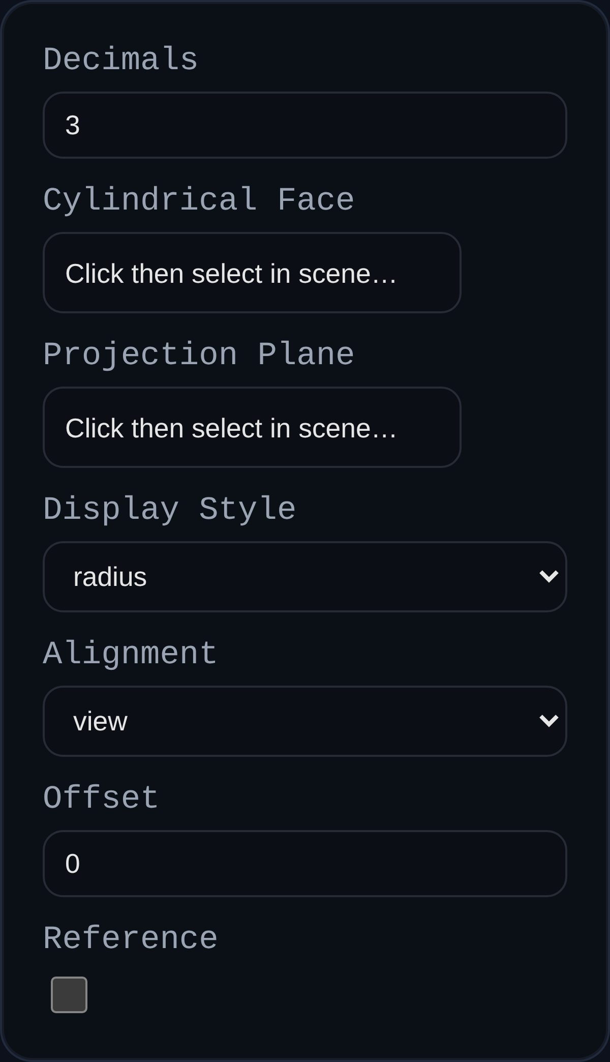
annotationID– optional persistent identifier.decimals– numeric precision; inherits the PMI modedimDecimalssetting when left blank.cylindricalFaceRef– cylindrical face reference used to extract the centerline and radius.planeRef– optional face or datum that defines the projection plane.displayStyle– chooseradiusordiameteroutput.alignment– align leader projection to the current view or a principal axis.offset– shifts the label outward from the cylindrical surface; dragging the label updates the stored offset.isReference– formats the value as a reference dimension.
Behaviour
- Automatically computes center point, radial vector, and arrow geometry for both radius and diameter callouts.
- Maintains associative links to the source cylinder; machining edits update the PMI value on regen.
- Supports interactive label dragging on the projection plane while preserving trace lines and offsets.
- Center markers and arrows scale with screen space to stay readable while orbiting.
Usage Tips
- Supply a projection plane when the default view produces misleading offsets, especially for angled holes.
- Use diameter display style (
Ø) for holes and radius display (R) for fillets to match common drawing conventions. - Pair with linear dimensions to fully define hole patterns and bolt circles in a single PMI view.