Linear Dimension
Status: Implemented
Linear dimensions measure the distance between two vertices and project the result into the active PMI view. Use them to document edge-to-edge spacing and critical offsets without altering model geometry.
Inputs
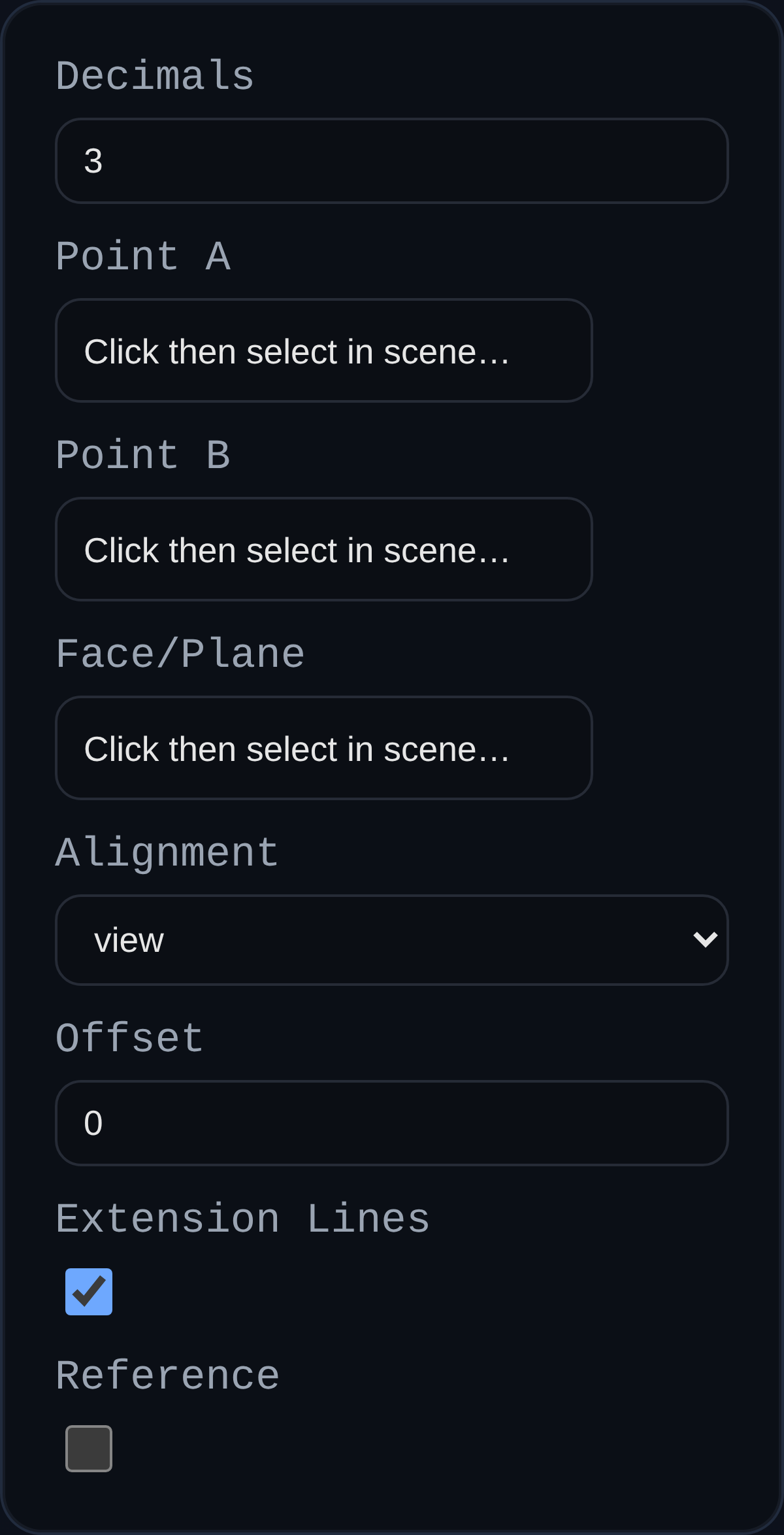
annotationID– optional identifier stored with the PMI payload.decimals– decimal precision; defaults to the PMI modedimDecimalspreference.aRefName/bRefName– vertex references that define the measured span.planeRefName– optional face or datum plane that controls projection.alignment– lock the dimension to the view plane or one of the global axes (XY, YZ, ZX).offset– distance to shift the dimension line away from the measured span; dragged labels update this value automatically.showExt– toggle extension lines from anchors to the offset dimension line.isReference– wraps the display text in parentheses when set.
Behaviour
- Distance is recomputed whenever anchor geometry updates; labels stay associative.
- Arrowheads and extension lines scale with screen distance so dimensions remain legible at any zoom.
- Labels can be dragged; the system captures the world position and extension offset for repeatable layouts.
- Dimensions respect PMI inspector formatting hooks such as
formatReferenceLabelfor dual-units or reference styling.
Usage Tips
- Pick a projection plane when the default view alignment produces ambiguous results (e.g., angled faces).
- Use
alignment = viewwith the PMI triad to quickly dimension sketch-like layouts, or axis alignment to match drawing standards. - Combine with reference dimensions to communicate non-driving measurements without cluttering the model.