Sheet Metal Contour Flange
Status: Implemented
Contour Flange converts an open sketch (or connected edge chain) into a sheet metal body by sweeping a rectangular strip along the curves. The tool inserts bend radii wherever adjacent segments meet so downstream features inherit accurate manufacturing parameters.
Inputs
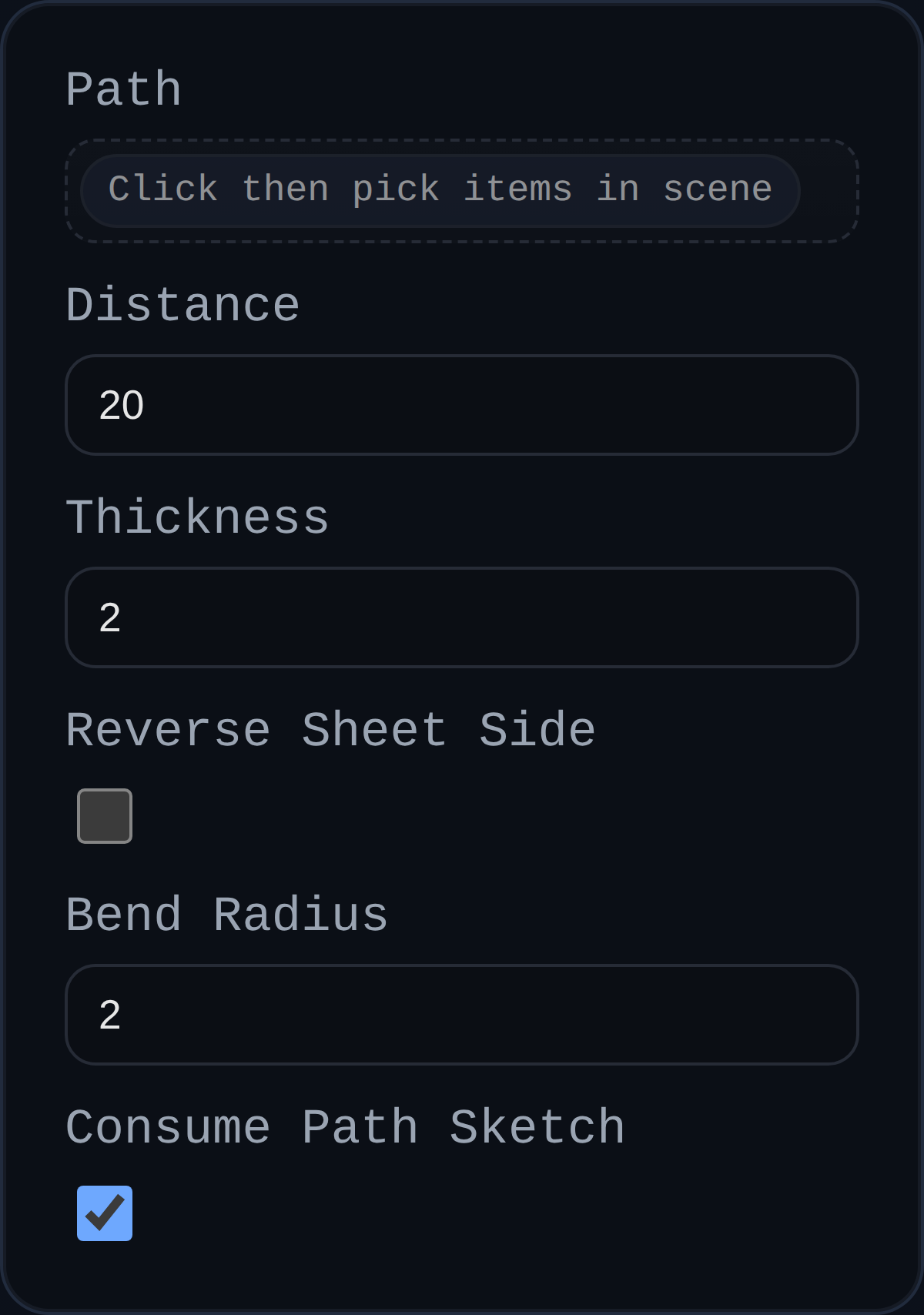
path– Open sketch or connected edges describing the contour path. Paths are auto-sorted and filleted.distance– Width of the strip measured perpendicular to the selected path. Negative values flip the strip direction.thickness– Sheet-metal thickness, extruded normal to the sketch plane.bendRadius– Default inside bend radius used to round every sharp joint.reverseSheetSide– Flip which side of the sketch plane receives material (handy when the automatic side is opposite your intent).consumePathSketch– Optional checkbox to remove the driving sketch after the body is created (disable to keep it visible for downstream edits).
Behaviour
- Builds a rectangular sweep profile (
distance × thickness) anchored to the selected path, then usesBREP.SweepinpathAlignmode so bends follow the path curvature. - Automatically fillets the path with the supplied bend radius (so two-line sketches become manufacturable flanges without extra work).
- Removes consumed sketch groups once the flange body is generated.
- Annotates created solids with
userData.sheetMetalmetadata (base type, thickness, bend radius, sheet side, etc.) for downstream flange/cutout operations.