Hole
Status: Implemented
Adds drilled-style holes with optional countersink or counterbore. The feature accepts a sketch or one or more vertices as placement inputs and produces separate holes for every point selected (sketch center P0 is ignored by default).
Inputs
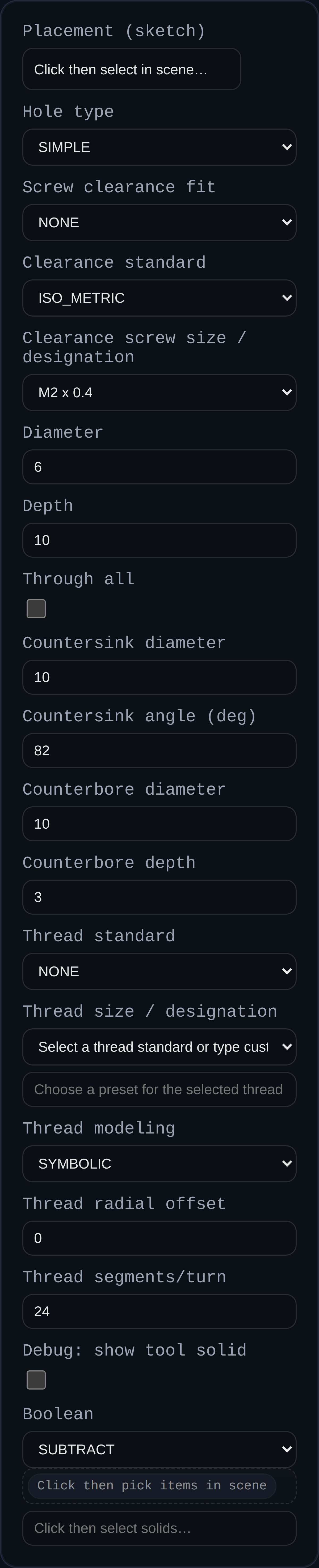
- Placement (sketch or points) – Pick a sketch (all sketch points except the auto center) or select individual vertices. Each point creates its own hole.
- Hole type –
SIMPLE,COUNTERSINK, orCOUNTERBORE. - Diameter – Core hole diameter.
- Depth – Total hole depth (straight portion). For countersink/counterbore, the sink/bore occupies part of this total; the straight leg shortens accordingly.
- Through all – If enabled, cuts through the entire target; depth is ignored.
- Countersink diameter / angle – For countersinks.
- Counterbore diameter / depth – For counterbores.
- Thread standard / designation – When
Hole typeisTHREADED, choose a standard (ISO, Unified, etc.) and a size (e.g.,#10-24 UNC). - Thread modeling –
SYMBOLIC(fast preview) orMODELED(helical geometry). - Thread radial offset – Clearance offset applied to crest/root.
- Thread segments/turn – Controls modeled thread tessellation (ignored for symbolic).
- Boolean – Optional boolean operation (defaults to subtracting from the target solid).
Notes
- When a sketch is selected, the feature automatically gathers its sketch points (except P0) and places one hole per point.
- Countersink/counterbore depth is part of the total depth: e.g., total depth 4 with counterbore depth 1 yields a 1‑unit bore plus a 3‑unit straight leg.
- Hole metadata (center, normal, dimensions, and source selection) is stored for PMI hole callouts.
- Threaded holes:
- Enabling “Debug: show tool solid” visualizes the tool bodies (cylinder/cone/thread core) used for the boolean.
- Symbolic threads cut the minor-diameter cylinder and add dashed overlay rings at the major diameter plus a centerline. This keeps previews lightweight but communicates thread extents. - Modeled threads build helical geometry; for internal threads, the helix extends one pitch beyond both ends to avoid flat terminations. - Thread metadata (standard, designation, pitch, modeled vs symbolic, offsets) is attached to faces for downstream references.