Angle Constraint
Status: Implemented
Angle constraints rotate components until the measured angle between two references matches a specified target. They work on face normals or edge directions and are ideal for setting hinge offsets or maintaining draft angles during assembly.
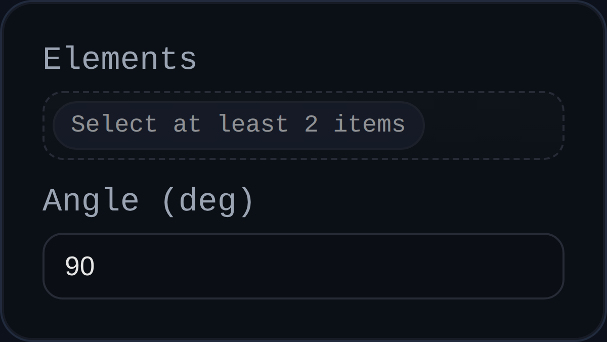
Inputs
id– solver-assigned identifier (for exampleANGL3).elements– two selections. Faces use their resolved normals; edges use the edge direction extracted from geometry.angle– desired signed angle in degrees. The implementation normalises the value to the[-360, 360]range before solving.
Behaviour
- Resolves each selection to a component, origin, and direction vector. Faces defer to
resolveParallelSelection(), while edges derive a direction from geometry or PMI utilities. - Rejects selections that cannot provide a direction, that belong to the same component, or that are not both attached to assembly components.
- Measures the current signed angle, keeps both radian and degree readings in
persistentData, and compares the angular error against either the suppliedcontext.angleToleranceor a tolerance derived from the solver's positional tolerance. - Decides how to distribute the correction: if both components can move it splits the delta angle evenly; otherwise the entire adjustment is applied to the movable component.
- Uses
computeRotationTowards()plus the solverrotationGainto cap the per-iteration rotation step (bounded byMAX_ROTATION_PER_ITERATIONfrom the parallel alignment utilities). - Records every applied quaternion in
lastAppliedRotationsfor downstream diagnostics.
Usage Tips
- Pair Angle with Coincident or Distance when you need to control both the pivot point and the orientation.
- Use a smaller
rotationGainfor stiff systems or when starting far from the target angle; it helps prevent oscillation. - If the constraint refuses to solve, confirm both selections resolve to different components and that each exposes a valid direction vector.